Skip to content
PCBFIX Micro-soldering workshop · Veldhoven

Component-level hardware repair // no upgrades — repair only

Faulty SSD, NVMe or RAM? We repair at printed-circuit-board level.

An SSD that suddenly no longer shows up in BIOS or Windows. A DDR5 module that lost a tiny SMD component while a heatsink was being fitted. That is no reason to throw the hardware away — and certainly no reason to hand it to a data-recovery lab where the call-out fee alone runs € 800 or more. We measure the board, locate the short circuit and re-solder the defective component under a stereo microscope.

Or use the intake form — reply within one business day

Workbench · live specifications

Smallest component size
0201 / 0402 SMD
Typical faults
Short circuit · faulty PMIC · knocked-off capacitors · damaged gold fingers
Your data
100% intact — we only touch the power circuit
Policy
No cure, no pay if controller or NAND is beyond repair
The workshop · Veldhoven STEREO MICROSCOPE · JBC
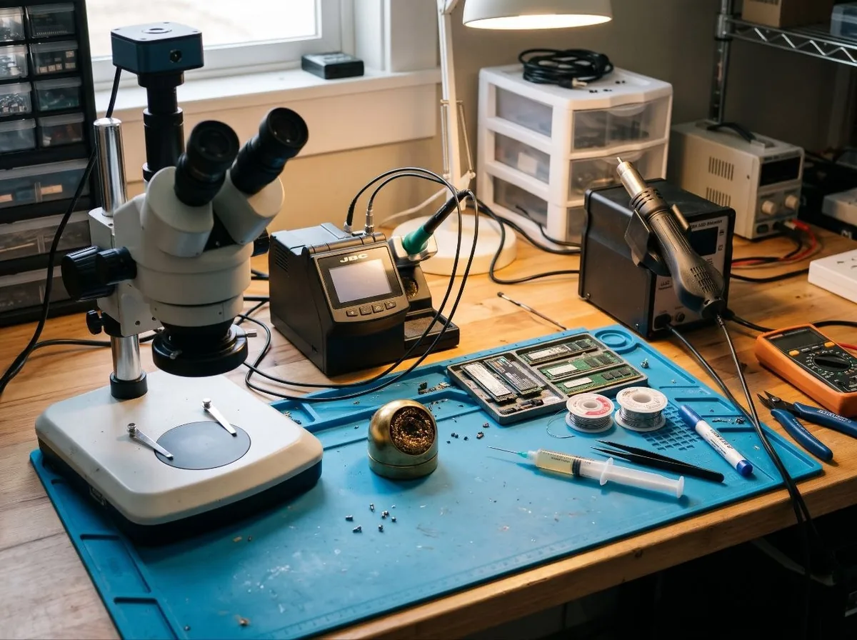
The lab workbench: stereo microscope with camera, JBC soldering station, hot-air rework station and NVMe and memory modules on an anti-static mat.

[SEC-02] // Interactive diagnosis

Fault analysis in three steps

01 Hardware

02 Symptom

03 Assessment

Awaiting input

Indicative assessment based on your answers — the final diagnosis follows once the submitted photo has been measured.

[SEC-03] // Repair cases

Under the microscope, documented

CASE 01 · shotMACRO
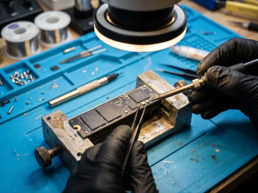
A replacement SMD component being soldered onto an M.2 NVMe SSD, held in a jig, under a ring-light microscope.

CASE 01

M.2 NVMe — short circuit (PMIC & capacitor)

A shorted ceramic capacitor on the 3.3 V rail drags down the supply of the entire drive: the controller never powers up and the SSD stays invisible in BIOS. The defective capacitor is removed under the microscope and replaced with a new 0402 part — the rail returns to 3.29 V and the data is fully readable again, with nothing lost.

BEFORE0.3 Ω → GND (short)

AFTER2.1 kΩ — rail healthy
CASE 02 · shotMULTIMETER
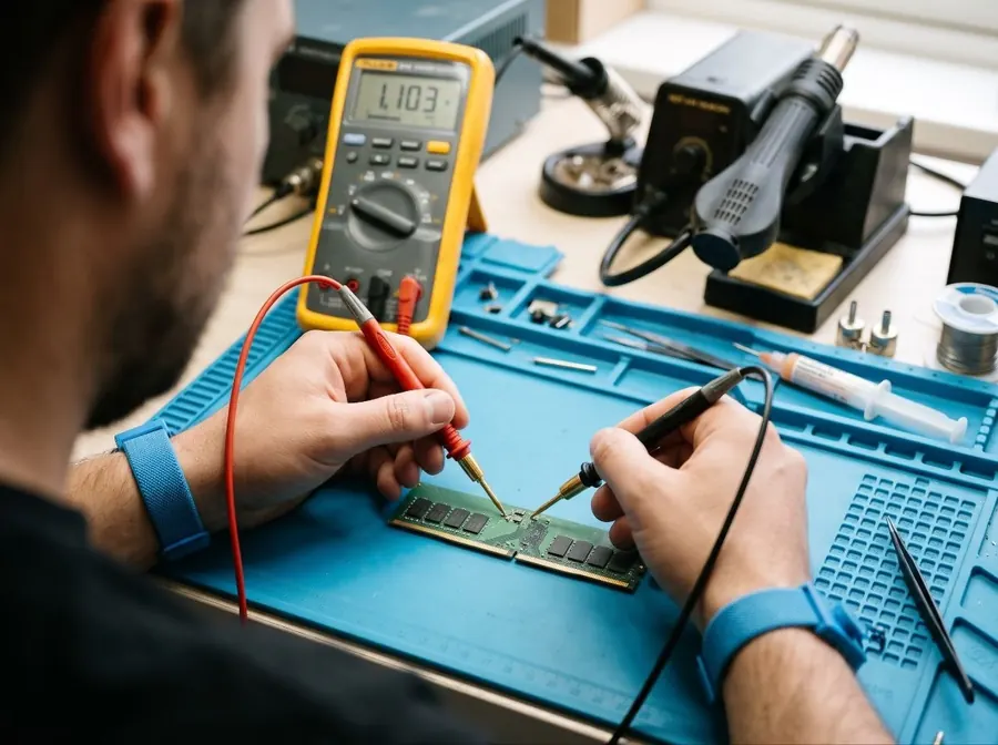
A DDR5 memory module being measured with a multimeter during a continuity check on the supply rail.

CASE 02

DDR5 — SMD knocked off while fitting a heatsink

While tightening a heatsink, a 0402 resistor broke off right next to the gold contacts. The motherboard halts the boot sequence with the DRAM-LED lit. The resistor is re-attached under the stereo microscope using lead-free solder; continuity is verified with a multimeter. The module runs stable on its XMP profile again.

CONTINUITY BEFOREOPEN (no connection)

CONTINUITY AFTER< 1 Ω — restored

CASE 03 · shotFINE WORK
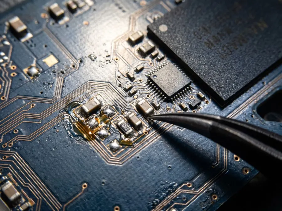
Fine work: a replacement SMD component being positioned on the PCB with precision tweezers.

CASE 03

Damaged PCB traces & pads

A torn-off pad and two broken copper traces near the NAND connector. The traces are bridged with 0.1 mm copper wire, secured and finished with UV lacquer against moisture and vibration. After the repair: a full drive check with a healthy SMART status and one hundred percent readable sectors.

TRACES 1 & 2 BEFOREBROKEN

AFTER BRIDGE + TESTSMART: GOOD · 100% READABLE

[SEC-04] // Honest boundaries

What we DO and DO NOT repair

YES — recoverable

  • Blown fuses and diodes
  • Faulty PMIC and voltage-regulator chips
  • Shorted ceramic capacitors
  • Missing or knocked-off SMD components
  • Broken connectors and contacts
  • Broken traces and pads

NO — beyond repair

  • Physically cracked NAND flash chips
  • Internally burnt-out main controller (visible burn hole in the chip)
  • Firmware corruption without an electronic fault

Note — these cases carry no repair costs and no diagnosis fee either — you only pay the return shipping. Do you decline after a successful diagnosis? Then only the DIAG-01 fee of € 35 applies.

[SEC-05] // Logistics & transparency

From photo to measurement report — in three steps

  1. Step 01

    Photo & intake

    Send a sharp photo of the PCB via WhatsApp or the intake form. Within one business day you receive an honest price indication — upfront, with no surprises afterwards.

  2. Step 02

    Drop off or ship

    Drop it off by appointment in Veldhoven, or ship it safely as a letterbox parcel with Track & Trace. After the intake you receive a reference number to include with the parcel.

  3. Step 03

    Measurement, repair & test

    Repaired under the stereo microscope, then re-measured with a multimeter on every supply rail and tested for full readability. You receive a short measurement report with the before and after values. After payment (iDEAL or payment request) we return your hardware safely in anti-static packaging via PostNL Track & Trace — letterbox parcel € 4.25 / parcel € 6.95.

100% Data privacy

We repair only the electronics on the board. As soon as the drive powers up again and appears in our test system (SMART/partition table), the repair is a success. We never open, copy or view personal folders or files — the NAND flash chips stay fully intact.

Rates — indicative 2026

TAR-05

Indicative rates for component-level repair
Code Service Rate
DIAG-01 Diagnosis & fault localisation (fully deducted upon repair) € 35
REP-01 SMD component replacement (resistor, capacitor, diode) € 55–75
REP-02 PMIC or voltage regulator replacement € 85–110
REP-03 Trace or pad repair (per trace) € 60–90
REP-04 Connector or gold-finger repair from € 65
NCP-01 No cure, no pay — controller or NAND beyond repair € 0 repair charge

No cure, no pay — repair not possible? Then you pay € 0: only the return shipping.

Do you decline after a successful diagnosis? Then the DIAG-01 diagnosis fee of € 35 applies.

All amounts include VAT. You always receive a fixed quote upfront; soldering only starts after your approval.

[SEC-06] // Intake

Register for repair

PCB macro photos

Drag photos here or click to select

JPG · PNG · HEIC — max. 5 files, 8 MB each

    Delivery preference *

    No repair without your approval of the quote.